How to Draw Constellation Diagram
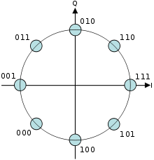
An 8-PSK. Information transmitted co-ordinate to the scheme described in the in a higher place diagram is encoded as one of 8 "symbols", each representing 3 bits of data. Each symbol is encoded as a different stage shift of the carrier sine moving ridge: 0°, 45°, ninety°, 135°, 180°, 225°, 270°, 315°.
A constellation diagram is a representation of a signal modulated by a digital modulation scheme such as quadrature amplitude modulation or phase-shift keying.[i] It displays the signal as a two-dimensional xy-aeroplane besprinkle diagram in the circuitous plane at symbol sampling instants. The bending of a point, measured counterclockwise from the horizontal axis, represents the phase shift of the carrier wave from a reference stage. The distance of a point from the origin represents a measure of the amplitude or ability of the signal.
In a digital modulation system, information is transmitted as a series of samples, each occupying a uniform time slot. During each sample, the carrier wave has a constant amplitude and phase, which is restricted to one of a finite number of values. So each sample encodes ane of a finite number of "symbols", which in turn represent one or more binary digits (bits) of information. Each symbol is encoded as a dissimilar combination of amplitude and phase of the carrier, so each symbol is represented by a signal on the constellation diagram, called a constellation point. The constellation diagram shows all the possible symbols that can be transmitted by the arrangement as a drove of points. In a frequency or phase modulated signal, the indicate amplitude is constant, and so the points prevarication on a circumvolve around the origin.
The carrier representing each symbol tin be created past adding together dissimilar amounts of a cosine wave representing the "I" or in-stage carrier, and a sine wave, shifted by xc° from the I carrier called the "Q" or quadrature carrier. Thus each symbol can be represented by a complex number, and the constellation diagram can be regarded as a complex plane, with the horizontal real centrality representing the I component and the vertical imaginary axis representing the Q component. A coherent detector is able to independently demodulate these carriers. This principle of using 2 independently modulated carriers is the foundation of quadrature modulation. In pure phase modulation, the phase of the modulating symbol is the phase of the carrier itself and this is the best representation of the modulated signal.
A 'signal space diagram' is an ideal constellation diagram showing the right position of the indicate representing each symbol. Later on passing through a communication channel, due to electronic noise or distortion added to the bespeak, the amplitude and phase received by the demodulator may differ from the correct value for the symbol. When plotted on a constellation diagram the point representing that received sample will be first from the correct position for that symbol. An electronic test instrument called a vector signal analyzer tin can display the constellation diagram of a digital signal by sampling the signal and plotting each received symbol as a betoken. The result is a 'ball' or 'cloud' of points surrounding each symbol position. Measured constellation diagrams can be used to recognize the type of interference and distortion in a indicate.
Interpretation [edit]

A constellation diagram for rectangular 16-QAM.

A spectrum analyzer software using different views to show a QAM 4096 constellation diagram

The constellation as received, with noise added.
The number of constellation points in a diagram gives the size of the "alphabet" of symbols that can be transmitted by each sample, and so determines the number of bits transmitted per sample. It is normally a power of 2. A diagram with 4 points, for case, represents a modulation scheme that can separately encode all 4 combinations of 2 bits: 00, 01, x, and xi, and and then can transmit two bits per sample. Thus in full general a modulation with constellation points transmits bits per sample.


Afterwards passing through the communication channel the signal is decoded by a demodulator. The office of the demodulator is to classify each sample as a symbol. The set of sample values which the demodulator classifies as a given symbol can be represented by a region in the plane drawn around each constellation betoken. If noise causes the point representing a sample to stray into the region representing another symbol, the demodulator will misidentify that sample every bit the other symbol, resulting in a symbol fault. Most demodulators choose, as its estimate of what was actually transmitted, the constellation bespeak which is closest (in a Euclidean altitude sense) to that of the received sample; this is called maximum likelihood detection. On the constellation diagram these detection regions tin can be easily represented by dividing the plane by lines equidistant from each adjacent pair of points.
One half the distance between each pair of neighboring points is the amplitude of additive noise or distortion required to cause one of the points to be misidentified as the other, and thus crusade a symbol error. Therefore, the further the points are separated from one some other, the greater the noise amnesty of the modulation. Practical modulation systems are designed to maximize the minimum noise needed to cause a symbol error; on the constellation diagram this means that the distance between each pair of next points is equal.
The received signal quality can exist analyzed by displaying the constellation diagram of the signal at the receiver on a vector point analyzer. Some types of distortion evidence up equally characteristic patterns on the diagram:
- Gaussian dissonance causes the samples to land in a random brawl about each constellation bespeak
- Non-coherent single frequency interference shows as samples making circles about each constellation point
- Stage noise shows as constellation points spreading into arcs centered on the origin
- Amplifier compression causes the corner points to move towards the center
A constellation diagram visualises phenomena like to those an middle pattern does for one-dimensional signals. The eye pattern can exist used to see timing jitter in one dimension of modulation.
See also [edit]
- Error vector magnitude
- Centre diagram
- Modulation error ratio
- Quadrature amplitude modulation
References [edit]
- ^ ANDREW Due south. TANENBAUM. COMPUTER NETWORKS. PRENTICE HALL. pp. 131–132. ISBN0-13-212695-8.
How to Draw Constellation Diagram
Source: https://en.wikipedia.org/wiki/Constellation_diagram
Post a Comment for "How to Draw Constellation Diagram"